Leak detection
Pipeline leak detection is used to determine if and in some cases where a leak has occurred in systems which contain liquids and gasses. Methods of detection include hydrostatic testing after pipeline erection and leak detection during service.
Pipeline networks are the most economic and safest mode of transportation for oil, gases and other fluid products. As a means of long-distance transport, pipelines have to fulfill high demands of safety, reliability and efficiency. If properly maintained, pipelines can last indefinitely without leaks. Most significant leaks that do occur are caused by damage from nearby excavation equipment, therefore it is critical to call authorities prior to excavation to assure that there are no buried pipelines in the vicinity. If a pipeline is not properly maintained, it can begin to corrode slowly, particularly at construction joints, low points where moisture collects, or locations with imperfections in the pipe. However, these defects can be identified by inspection tools and corrected before they progress to a leak. Other reasons for leaks include accidents, earth movement, or sabotage.
The primary purpose of leak detection systems (LDS) is to assist pipeline controllers in detecting and localizing leaks. LDS provide an alarm and display other related data to the pipeline controllers in order to aid in decision-making. Pipeline leak detection systems are also beneficial because they can enhance productivity and system reliability thanks to reduced downtime and reduced inspection time. LDS are therefore an important aspect of pipeline technology.
According to the API document “RP 1130”, LDS are divided into internally based LDS and externally based LDS. Internally based systems utilize field instrumentation (for example flow, pressure or fluid temperature sensors) to monitor internal pipeline parameters. Externally based systems also utilize field instrumentation (for example infrared radiometers or thermal cameras, vapor sensors, acoustic microphones or fiber-optic cables) to monitor external pipeline parameters.
Rules and Regulations
Some countries formally regulate pipeline operation.
API RP 1130 “Computational Pipeline Monitoring for Liquids” (USA)
This recommended practice (RP) focuses on the design, implementation, testing and operation of LDS that use an algorithmic approach. The purpose of this recommended practice is to assist the Pipeline Operator in identifying issues relevant to the selection, implementation, testing, and operation of an LDS. LDS are classified into internally based and externally based. Internally based systems utilize field instrumentation (e.g. for flow, pressure and fluid temperature) to monitor internal pipeline parameters; these pipeline parameters are subsequently used for inferring a leak. Externally based systems use local, dedicated sensors.
TRFL (Germany)
TRFL is the abbreviation for “Technische Regel für Fernleitungsanlagen” (Technical Rule for Pipeline Systems). The TRFL summarizes requirements for pipelines being subject of official regulations. It covers pipelines transporting flammable liquids, pipelines transporting liquids that are dangerous for water, and most of the pipelines transporting gas. Five different kinds of LDS or LDS functions are required:
- Two independent LDS for continuous leak detection during steady-state operation. One of these systems or an additional one must also be able to detect leaks during transient operation, e.g. during start-up of the pipeline
- One LDS for leak detection during shut-in operation
- One LDS for creeping leaks
- One LDS for fast leak location
Requirements
API 1155 (replaced by API RP 1130) defines the following important requirements for an LDS:
- Sensitivity: An LDS must ensure that the loss of fluid as a result of a leak is as small as possible. This places two requirements on the system: it must detect small leaks, and it must detect them quickly.
- Reliability: The user must be able to trust the LDS. This means that it must correctly report any real alarms, but it is equally important that it does not generate false alarms.
- Accuracy: Some LDS are able to calculate leak flow and leak location. This must be done accurately.
- Robustness: The LDS should continue to operate in non-ideal circumstances. For example, in case of a transducer failure, the system should detect the failure and continue to operate (possibly with necessary compromises such as reduced sensitivity).
Steady-state and transient conditions
During steady-state conditions, the flow, pressures, etc. in the pipeline are (more or less) constant over time. During transient conditions, these variables may change rapidly. The changes propagate like waves through the pipeline with the speed of sound of the fluid. Transient conditions occur in a pipeline for example at start-up, if the pressure at inlet or outlet changes (even if the change is small), and when a batch changes, or when multiple products are in the pipeline. Gas pipelines are almost always in transient conditions, because gases are very compressible. Even in liquid pipelines, transient effects cannot be disregarded most of the time. LDS should allow for detection of leaks for both conditions to provide leak detection during the entire operating time of the pipeline.
Internally based LDS
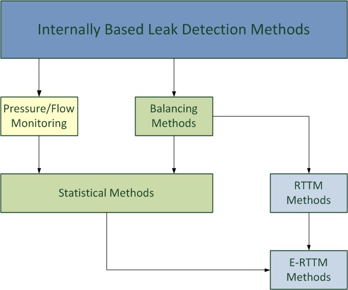
Internally based systems utilize field instrumentation (e.g. for flow, pressure and fluid temperature) to monitor internal pipeline parameters; these pipeline parameters are subsequently used for inferring a leak. System cost and complexity of internally based LDS are moderate because they use existing field instrumentation. This kind of LDS is used for standard safety requirements.
Pressure/Flow monitoring
A leak changes the hydraulics of the pipeline, and therefore changes the pressure or flow readings after some time. Local monitoring of pressure or flow at only one point can therefore provide simple leak detection. As it is done locally it requires in principle no telemetry. It is only useful in steady-state conditions, however, and its ability to deal with gas pipelines is limited.
Acoustic Pressure Waves
The acoustic pressure wave method analyses the rarefaction waves produced when a leak occurs. When a pipeline wall breakdown occurs, fluid or gas escapes in the form of a high velocity jet. This produces negative pressure waves which propagate in both directions within the pipeline and can be detected and analyzed. The operating principles of the method are based on the very important characteristic of pressure waves to travel over long distances at the speed of sound guided by the pipeline walls. The amplitude of a pressure wave increases with the leak size. A complex mathematical algorithm analyzes data from pressure sensors and is able in a matter of seconds to point to the location of the leakage with accuracy less than 50 m (164 ft). Experimental data has shown the method’s ability to detect leaks less than 3mm (0.1 inch) in diameter and operate with the lowest false alarm rate in the industry – less than 1 false alarm per year.
However, the method is unable to detect an ongoing leak after the initial event: after the pipeline wall breakdown (or rupture), the initial pressure waves subside and no subsequent pressure waves are generated. Therefore, if the system fails to detect the leak (for instance, because the pressure waves were masked by transient pressure waves caused by an operational event such as a change in pumping pressure or valve switching), the system will not detect the ongoing leak.
Balancing methods
These methods base on the principle of conservation of mass. In the steady state, the mass flow  entering a leak-free pipeline will balance the mass flow
  leaving it; any drop in mass leaving the pipeline (mass imbalance
  ) indicates a leak. Balancing methods measure and using flowmeters and finally compute the imbalance which is an estimate of the unknown, true leak flow. Comparing this imbalance (typically monitored over a number of periods) against a leak alarm threshold
  generates an alarm if this monitored imbalance. Enhanced balancing methods additionally take into account the change rate of the mass inventory of the pipeline. Names that are used for enhanced line balancing techniques are volume balance, modified volume balance, and compensated mass balance.
Statistical methods
Statistical LDS use statistical methods (e.g. from the field of decision theory) to analyse pressure/flow at only one point or the imbalance in order to detect a leak. This leads to the opportunity to optimise the leak decision if some statistical assumptions hold. A common approach is the use the hypothesis test procedure


This is a classical detection problem, and there are various solutions known from statistics.
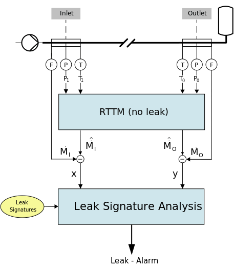
RTTM methods
RTTM means “Real-Time Transient Model”. RTTM LDS use mathematical models of the flow within a pipeline using basic physical laws such as conservation of mass, conservation of momentum, and conservation of energy. RTTM methods can be seen as an enhancement of balancing methods as they additionally use the conservation principle of momentum and energy. An RTTM makes it possible to calculate mass flow, pressure, density and temperature at every point along the pipeline in real-time with the help of mathematical algorithms. RTTM LDS can easily model steady-state and transient flow in a pipeline. Using RTTM technology, leaks can be detected during steady-state and transient conditions. With proper functioning instrumentation, leak rates may be functionally estimated using available formulas.
E-RTTM methods
E-RTTM stands for “Extended Real-Time Transient Model”, using RTTM technology with statistical methods. So, leak detection is possible during steady-state and transient condition with high sensitivity, and false alarms will be avoided using statistical methods.
For the residual method, an RTTM module calculates estimates  ,
,  for MASS FLOW at inlet and outlet, respectively. This can be done using measurements for pressure and temperature at inlet (
 ,
,  ) and outlet (
 ,
,  ). These estimated mass flows are compared with the measured mass flows , , yielding the residuals
  and
and 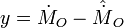 . These residuals are close to zero if there is no leak; otherwise the residuals show a characteristic signature. In a next step, the residuals are subject of a leak signature analysis. This module analyses their temporal behaviour by extracting and comparing the leak signature with leak signatures in a database (“fingerprint”). Leak alarm is declared if the extracted leak signature matches the fingerprint.
Externally based LDS
Externally based systems use local, dedicated sensors. Such LDS are highly sensitive and accurate, but system cost and complexity of installation are usually very high; applications are therefore limited to special high-risk areas, e.g. near rivers or nature-protection areas.
Digital Oil Leak Detection Cable
Digital Sense Cables consist of a braid of semi-permeable internal conductors protected by a permeable insulating moulded braid. An electrical signal is passed though the internal conductors and is monitored by an inbuilt microprocessor inside the cable connector. Escaping fluids pass through the external permeable braid and make contact with the internal semi-permeable conductors. This causes a change in the electrical properties of the cable that is detected by the microprocessor. The microprocessor can locate the fluid to within a 1-metre resolution along its length and provide an appropriate signal to monitoring systems or operators. The sense cables can be wrapped around pipelines, buried sub-surface with pipelines or installed as a pipe-in-pipe configuration.
Infrared Radiometric Pipeline Testing
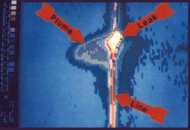
Infrared thermographic pipeline testing has shown itself to be both accurate and efficient in detecting and locating subsurface pipeline leaks, voids caused by erosion, deteriorated pipeline insulation, and poor backfill. When a pipeline leak has allowed a fluid, such as water, to form a plume near a pipeline, the fluid has a thermal conductance different from the dry soil or backfill. This will be reflected in different surface temperature patterns above the leak location. A high-resolution infrared radiometer allows entire areas to be scanned and the resulting data to be displayed as pictures with areas of differing temperatures designated by differing grey tones on a black & white image or by various colours on a colour image. This system measures surface energy patterns only, but the patterns that are measured on the surface of the ground above a buried pipeline can help show where pipeline leaks and resulting erosion voids are forming; it detects problems as deep as 30 meters below the ground surface.
Acoustic emission detectors
Escaping liquids creates an acoustic signal as they passes through a hole in the pipe. Acoustic sensors affixed to the outside of the pipeline create a baseline acoustic “fingerprint” of the line from the internal noise of the pipeline in its undamaged state. When a leak occurs, a resulting low frequency acoustic signal is detected and analysed. Deviations from the baseline “fingerprint” signal an alarm. Now sensors are having better arrangement with frequency band selection, time delay range selection etc. This makes the graphs more distinct and easy to analyse.There are other ways to detect leakage. Ground geo-phones with filter arrangement are very useful to pinpoint the leakage location. It saves the excavation cost. The water jet in the soil hits the inner wall of soil or concrete. This will create a feeble noise. This noise will decay while coming up on the surface. But the maximum sound can be picked up only over the leakage position. Amplifiers and filter helps to get clear noise. Some types of gases entered into the pipe line will create a range of sounds when leaving the pipe.
Vapour-sensing tubes
The vapour-sensing tube leak detection method involves the installation of a tube along the entire length of the pipeline. This tube – in cable form – is highly permeable to the substances to be detected in the particular application. If a leak occurs, the substances to be measured come into contact with the tube in the form of vapour, gas or dissolved in water. In the event of a leak, some of the leaking substance diffuses into the tube. After a certain period of time, the inside of the tube produces an accurate image of the substances surrounding the tube. In order to analyse the concentration distribution present in the sensor tube, a pump pushes the column of air in the tube past a detection unit at a constant speed. The detector unit at the end of the sensor tube is equipped with gas sensors. Every increase in gas concentration results in a pronounced “leak peak”.
Fibre-optic leak detection
At least two fibre-optic leak detection methods are being commercialized: Distributed Temperature Sensing (DTS) and Distributed Acoustic Sensing (DAS). The DTS method involves the installation of a fibre-optic cable along the length of pipeline being monitored. The substances to be measured come into contact with the cable when a leak occurs, changing the temperature of the cable and changing the reflection of the laser beam pulse, signalling a leak. The location is known by measuring the time delay between when the laser pulse was emitted and when the reflection is detected. This only works if the substance is at a temperature different from the ambient environment. In addition, the distributed fibre-optical temperature-sensing technique offers the possibility to measure temperature along the pipeline. Scanning the entire length of the fibre, the temperature profile along the fibre is determined, leading to leak detection.
The DAS method involves a similar installation of fiber-optic cable along the length of pipeline being monitored. Vibrations caused by a substance leaving the pipeline via a leak changes the reflection of the laser beam pulse, signalling a leak. The location is known by measuring the time delay between when the laser pulse was emitted and when the reflection is detected. This technique can also be combined with the Distributed Temperature Sensing method to provide a temperature profile of the pipeline.